Velomobile Board Computer
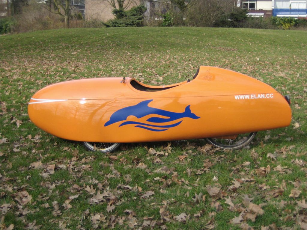
For those who don't know: a velomobile is a fully faired bicycle (trike). like the one in the picture The fairing reduces drag and protects against the elements.
On such a bike, it is not always easy to indicate direction so I wanted indicators, advanced LED front and tail light control, a spedometer and more. Integrated in one small device instead of separate components.
Requirements
Brainstorming is a nice way of collecting requirements.
Ehh... I mean brainstorming is a nice way of collecting tons of ideas that you are never able to implement at all ...
While driving back from the Fiets and Wandelbeurs (Feb 27, 2011) I start to write down some ideas together with Hans and Ellen:
- ANT speed/cadance/heartrate/power (SRM)
- Front light:3 different dimming modes (signal / normal / city)
- Tail light: use 1 LED for brake / fog / normal modes
- Programmable intensity modes (both PWM frequency and duty cycle)
- Indicators with options for running light and warning mode
with programmable blinking frequencies and intensity. - Indoor LED which can be used as trouble light also
- Battery monitor (showing remaining time) with built in charger
- Option of storing data (like the SRM PowerControl)
- GPS module with track logging
- USB 5V/1A output for charging phone etc.
- Large LCD with backlight for showing data:
Time, speed, trip/odo, heart reate, power and cadance. - Dome foil keyboard with function keys,
separate switches on steerer to control lights and indicators.
Besides these (hardware) requirements there are also some software (features) that were identified:
- 2 or 3 trip counters plus an ODO.
- maintenance counters to keep track of tire change etc.
- all parameters configurable via the keys on the device itself
- Battery status monitor to keep track of the charged and used capacity,
showing time remaining in current mode.
More requirements will pop up during the design.
Hardware Design
When there is one thing I am very sure of then it is that the hardware will change during the project. One thing that is fairly fixed is the microcontroller being used; an lpc1754 (or 1752/1756/167...), the rest of the design (especially LED controllers and battery management) is still unknown.
It is tempting to include a lot of the known stuff on one board to start with, or maybe even create a board that has multiple options and maybe a prototyping section as well. But in the end I decided it is best to start with a generic controller board that can be used for multiple projects. This is also a nice item to sell or give away.
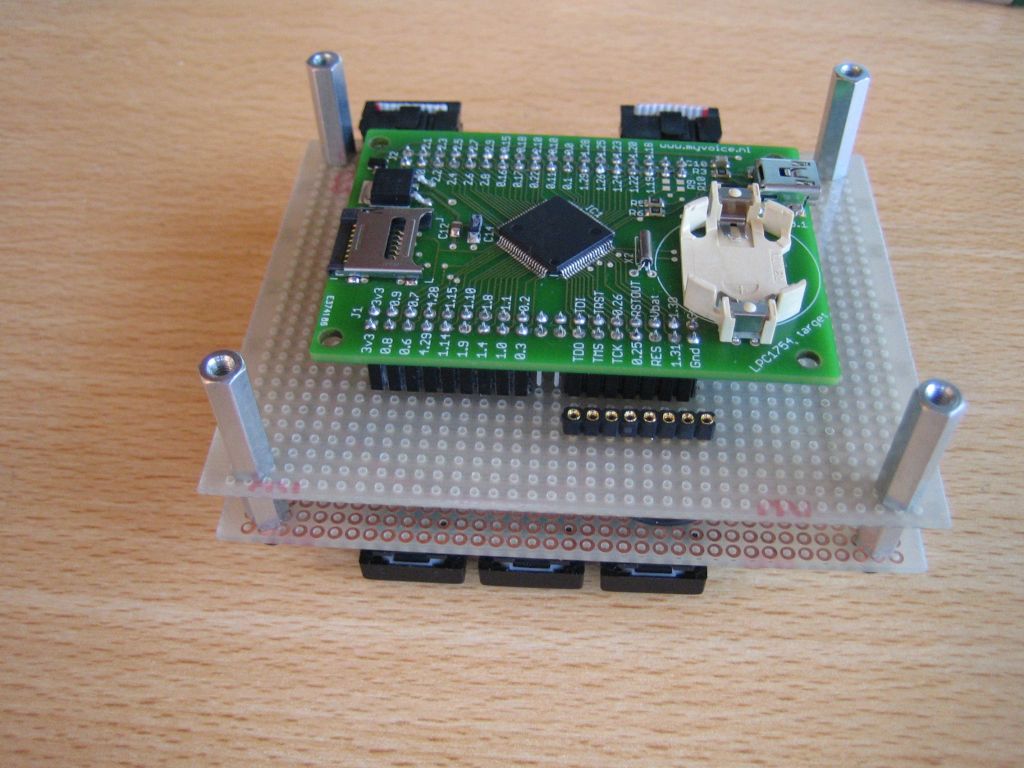
The resulting lpc1754 target board is a simple yet usefull board that accepts a selection of lpc17xx micrcontrollers so it is even kind of future proof.
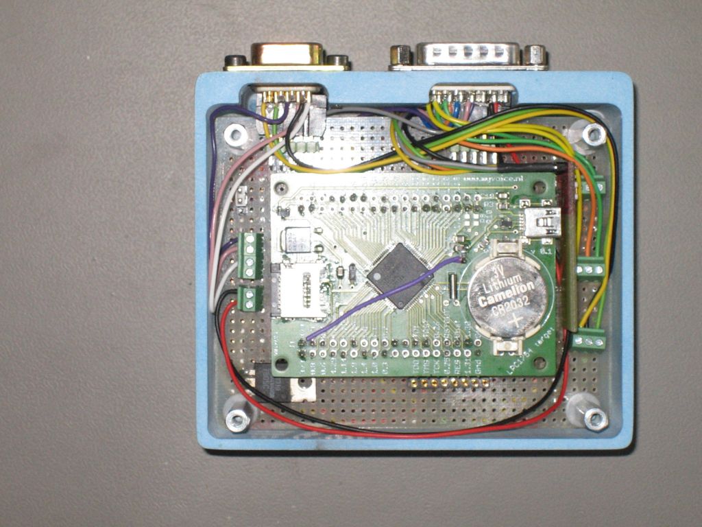
A sandwich of two perf boards with on one board an LCD plus some keys and on the other board the lpc1754 module form the basis of the first prototype.
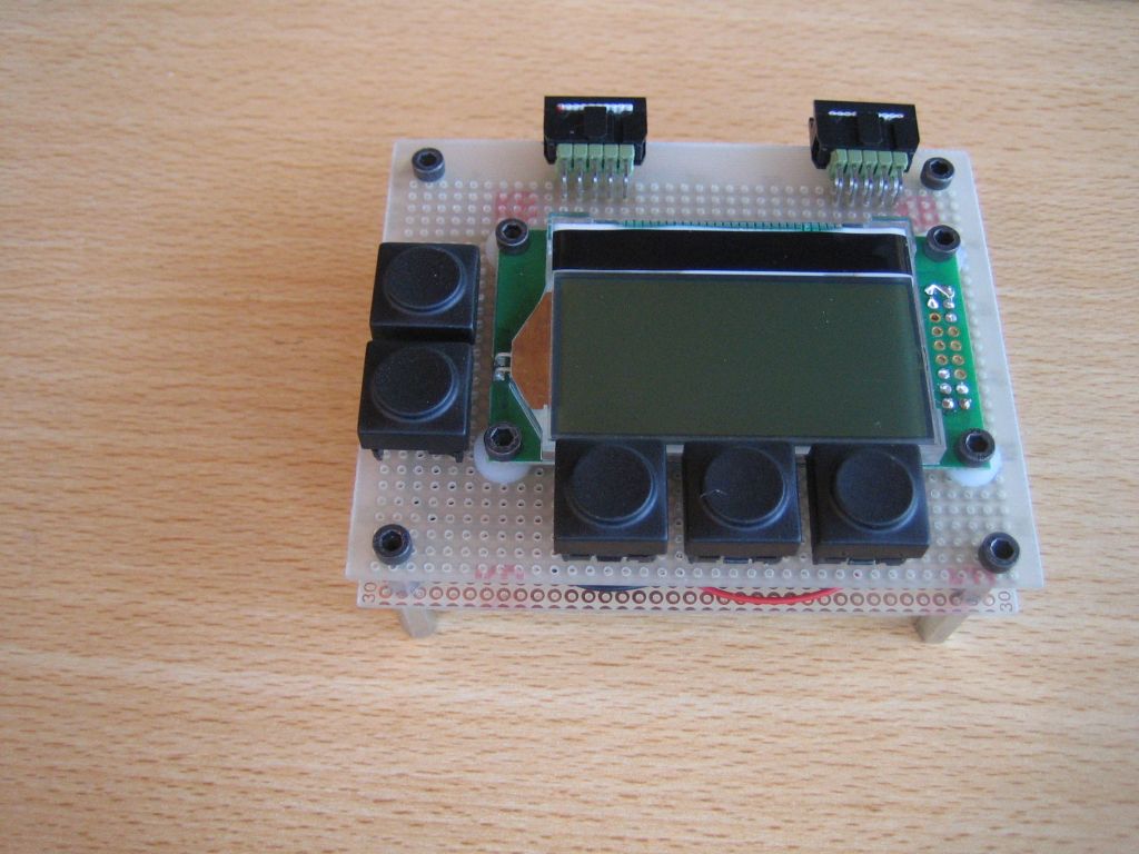
This first prototype still contains no battery charger and the LED drivers are standard modules used for flash lights.
Mechanics
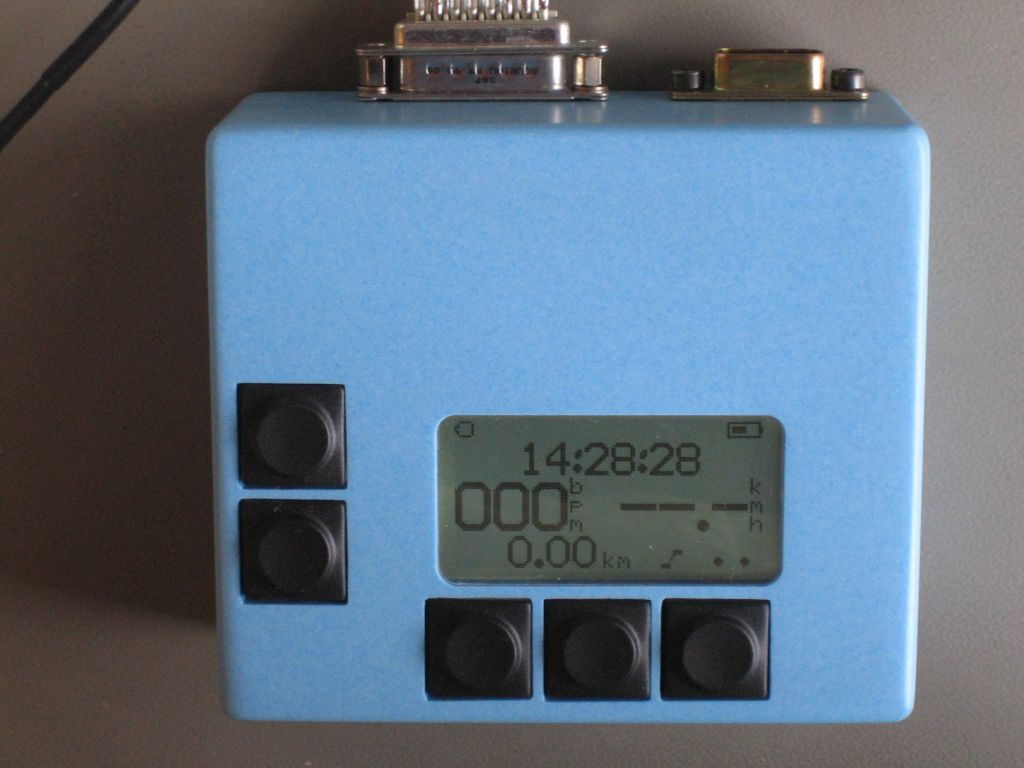
The nice thing on having all components available in a CAD tool like SolidWorks is that this enables me to find a housing that perfectly fits the electronics.
Of course this is just a first prototype, the final product will be much smaller with a foil containing a window for the LCD and dome keys embedded in the foil.
 |
 |