CAN Data Logger
I have been working on a number of automotive projects with CAN interfaces.
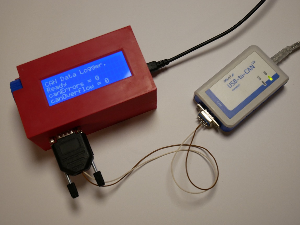
Logging of CAN data is always a must in these cases; I need the raw CAN information to validate if the system is working as expected. Most of the times this can be easily done using a laptop with a USB-CAN interface and I mostly use the USB-to-CAN interface from IXXAT for this.
Sometimes however, a Windows application is using the IXXAT as part of the system and other times using a laptop is not possible. My current project involves a go-kart and driving around on a kart with a laptop clamped between my elbows is not easy.
Just having a few days to get everything up&running means that plugging some Arduino boards on top of each other might be the fastest route to a workable solution.
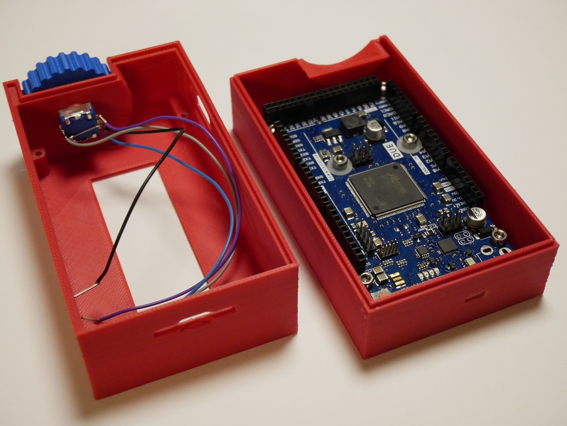
Arduino Due and some shields
To start of with; I am not an Arduino fan. I have had a few bad experiences with libraries that did not work as expected or contained bugs and there is no good development environment with project management and debugging capabilities.
But the Arduino family does contain some nice boards, shields and libraries for a lot of things. Some time ago I discovered the Arduino Due, a nice board with a fast processor with nice features.
A few mouse clicks later I had a good selection of boards: the Due, a CAN shield, an SD card shield, an LCD with optional I2C interface board and some extra stuff for my grab stock.
Unfortunately most Arduino shields are made for the Mega or UNO boards and these have 5V I/O logic whereas the Due, using an ARM core processor, has 3.3V I/O.
This means the selected data logging shield with an SD adapter and a real time clock is not usable. The real time clock (DS107) only works with 5V logic signals.
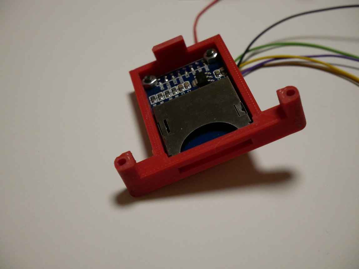
The selected SD adapter shield only works with 3.3V. The small PCB is perfect, it fits right in between the connectors of the CAN shield. This makes the stack of shields a bit lower and the case a bit smaller. I desoldered the straight header for the IO connections pin by pin; as soon as the pin gets hot it can be pulled through the plastic shrould easily.
I used a small frame to mount the SD adapter on the bottom of the display. This is easier than trying to print the mounting frame as part of the case.

LCDs are available with different interfaces: I2C, SPI or parallel are the most common interfaces for displays. The selected display has a 4/8 bits parallel interface and needs 6 wires. For prototyping I like to use as few wires as possible so I added an I2C I/O expander. The I/O expander fits directly on the back of the LCD and this allows me to add an LCD very quickly to any project.
The display needs 5V but the I/O expander can be used at 3.3V. Note that the I2C expander normally provides the power to the LCD so I removed this pin and soldered a wire directly to the LCD. The LCD now uses 5V with the I/O expander at 3.3V.
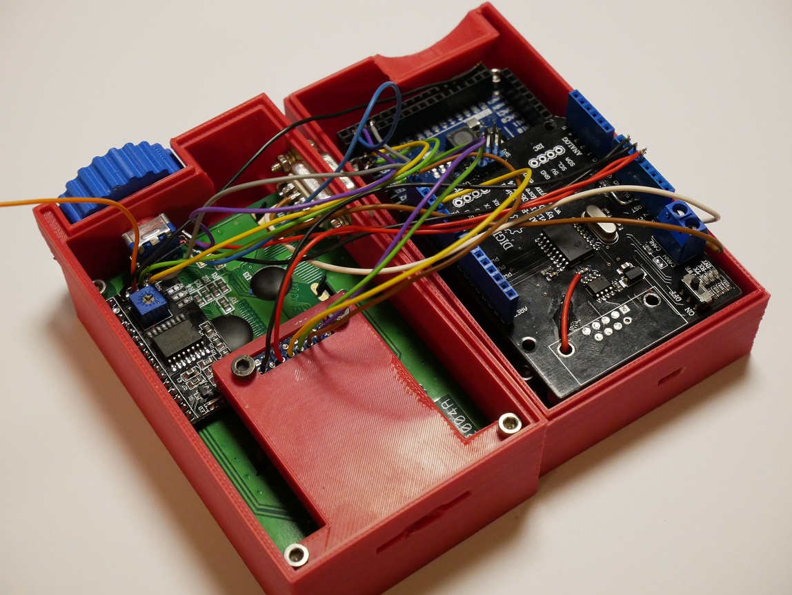
Here everything is mounted and wired. I removed the DB9 connector from the CAN Shield (it does not use the default pinout as specified by CANopen) and if you look closely you can see the modifications for the 3.3V power: next to the header with 3.3/5V from the Arduino and a separate 5V line to the CAN tranceiver.
If you do this, do not forget to cut the 5V trace from the 6-pin SPI connector. The shield gets 5V from both connectors!!!
After a bit of a struggle while closing the case, all wires stay inside.
I gambled a bit on the total height of the case and the snap-fit closing mechanism but both came out fairly nice. A next version of the case will use a snap-fit on the side with the SD slot and a screw behind the blue knob.
No batteries
When I stacked all the board together, I had a hard time figuring out where to place the battery. I have some small Lithium polymer batteries but this means adding a boost converter to get 5V, a power switch and a charger. Since this is just a prototype that needs to be finished quickly I decided to drop the battery and use a USB power bank.
This decision may have saved me some trouble at the airport; with every piece of custom electronics in my bag I got a question if it contains (lithuim) batteries. USB power banks are accepted but as soon as you have custom electronics with litium batteries they get scared ...
Software
Having the Arduino community is a big advantage. The library for the LCD module works out-of-the-box, as does the SD-card library and the CAN shield is compatible with the CANbus library from SparkFun.
A simple application is copy and pasted together from the different examples that come with the libraries and it does not take long before I have a simple test-program that captures CAN packets and writes the data into a file.
Now the fun begins ...
I want to be sure that no CAN packets are "lost in translation" so I start testing by flooding the CAN bus with packets. The logic analyzer is used to verify system performance. I monitor the CAN bus and use a few digital output pins to monitor how long it takes to read data from the CAN shield and to write to the SD card.
Reading the packets from the CAN shield is fine; it takes less than 100µs to read a packet over SPI and about 130µs to send data to the SD library.
To the library ... Looking further I see this is only collecting data in memory but as soon as a block is complete, it takes over 4ms to write the block to the SD card. As more data must be written, the FAT system must be maintained and on regular intervals the time spent in the SD card library increases to 8-16ms and sometimes even 85ms.
The CAN interface only buffers 2 or 3 messages so this means that overrun errors are occuring at regular intervals.
I decide to use an interrupt routine to get the data from the CAN shield and place it in a buffer, the main loop now only needs to check the buffer and write the SD card. This does however mean that the SD card must use a different SPI interface than the CAN shield.
The Atmel SAM3X processor on the Due has 2 USARTs with SPI capabilities, unfortunately there is no support for this (yet) in the standard libraries. Since I am not the first one investigating this option it does not take too long to find an example of how to use this. Changing the SD library to use this new USART-SPI mode was a bit more challenging.
References
The CANbus library from SparkFun (github.com/sparkfun/SparkFun_CAN-Bus_Arduino_Library) contains the interface towards the mcp2515.
TinyTronics provides a link to the library for the I2C display interface. This is not yet used in the application but I plan to show some statistics about number of packets received, bus load etc. It will also be used to control the user interface and to get some feedback on starting and stopping of the application.
The Arduino forum provided the information needed in order to make changes to the SD library for the USART (Serial2) in SPI mode.
The CAN data logger code can be found here. This is just a very crude test program to log data during 5s to allow me to validate the application.
The application uses a timer with an interrupt to provide a 1ms timestamp and an interrupt to read the CAN shield. Pins 6 and 7 are used to show the time spent in the CAN interrupt and the time spent to write the data to the SD card.
Testing
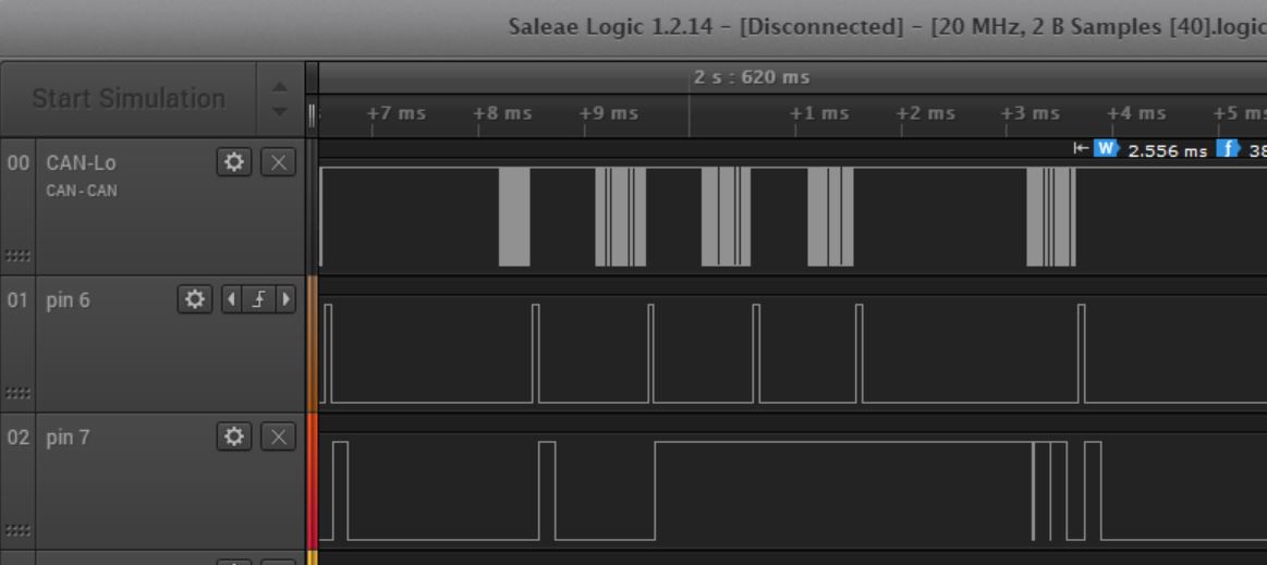
The image shows what happens when the SD card is taking more time.
The top line shows the CAN data; 5 packets are being transmitted on the bus. Pin6 is used to see that the data is being read by the processor and the line below (pin7) shows the SD library activity.
As the second CAN message is received, it takes about 3.5ms to write the data to the SD card and during this time 2 more CAN messages are being received. The short negative spikes at the end of the 3.5 ms period on pin7 show that these packets are transferred to the SD library (stored in it's memory buffer).
Shopping list
- Arduino Due
- MCP2515 CAN shield
- 20x4 character LCD module
- LCD I2C module
- SD adapter
- Rotary encoder
- DB9 connector
Since some time, TinyTronics also delivers 3D printer filament (1.75mm only) so while ordering I also ordered some "hot red" ASA for the case. ASA is an engineering material like ABS but it is easier to print with, and more UV stable than ABS. Apart from a little slicer quirk with missing support the print quality is good.
Next time I will ...
After finishing a project there are always these thing that you would do different next time.
Overall I am fairly statisfied with the result but I do not like the fancy knob on the rotary encoder. The idea was nice but looking at the final result I think I will change this for a next project.
The case is a bit too brick-like. It's 65 x 115 x 60 mm and 10~15mm is used for the CAN Shield with the tall dual headers. If I can remove the CAN shield, this reduces the height of the case to 45mm. Since the SAM3X on the Arduino Due has an on-board CAN device, this should be possible. The only reason not to do this right now, was the library support and the fact that I used this CAN shield before so I know that this works.
I actually prefer a graphical LCD over the 20x4 character LCD. A graphical LCD gives more options for an advanced interface with bar graphs, bitmaps and different font sizes but the character LCD is good enough if just used as a status display.
On the software side there are still a lot of features I like to add. One of this things I like to do, is to add a playback function. Being able to monitor a real life system and then use this data for testing and debugging purposes is something that my current CAN test-tool lacks.