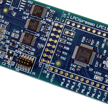
The LPC1754 target board
This board is a bit larger than the original LPCXpresso modules from Embedded Artists but has some extra features not found on the LPCXpresso modules:
- My 'own' processor
If the final hardware uses another variant than the lpc1769 then the board should contain the same MCU.
The lpc1754 has no Ethernet interface and misses some other things found in the lpc1769 but therefore it is less power hungry and also cheaper (the chip, not the board...) - a USB (device) connector
I am becoming a fan of the USB interface and a number of my project already include a USB interface so this board also has to support USB connectivity. - Battery backup
The real time clock needs a battery to back-up its time when not powered. Somehow it seemed to make sense to me to place the backup battery on the module itself. - micro-SD card connector
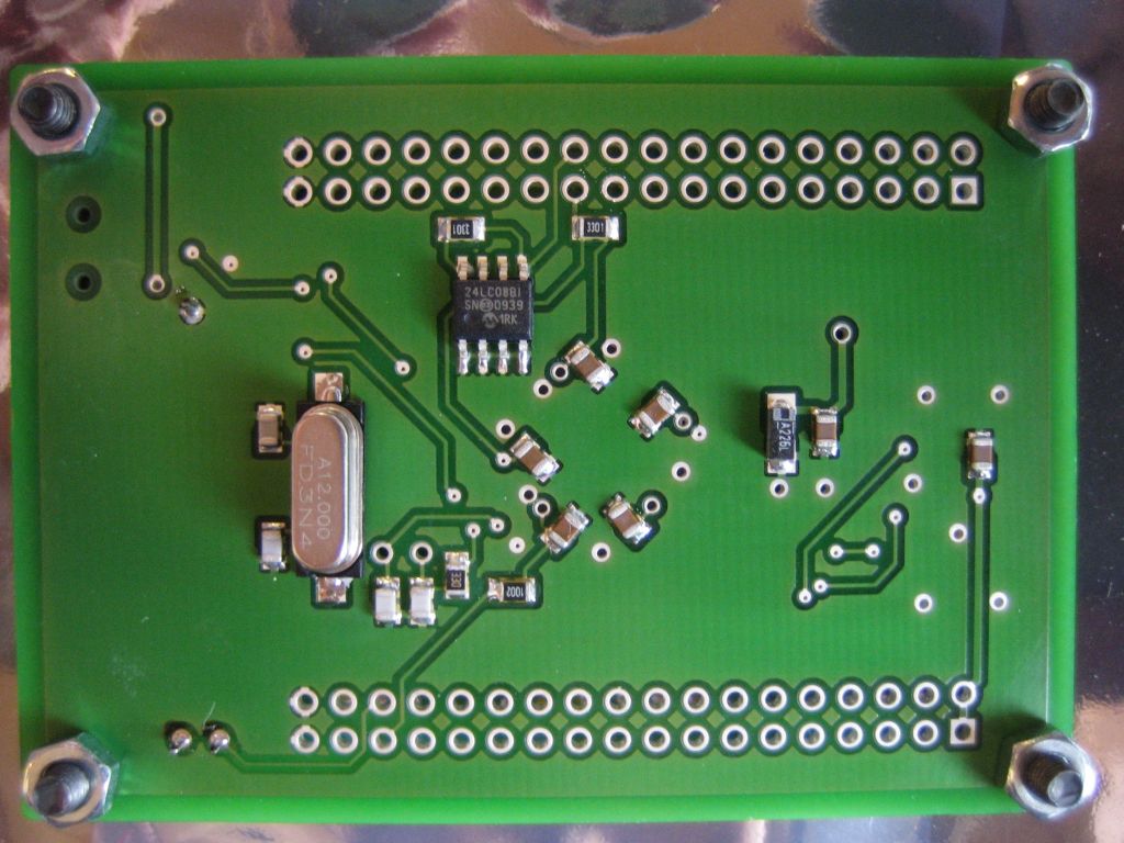
For a project I needed to store larger quantities of data, An SPI Flash is faster and takes less board space but is almost as expensive as a micro SD connector and an SD card. The advantage of being able to swap the card, store data in a standard (FAT) filesystem and being able to read the card from a PC made me choose for the SD card solution. - Small (1kB) I2C EEPROM
Very usefull to store configuration data/calibration values etc.
I actually discovered that some of the newer LPCXpresso modules also contain an EEPROM.
As an added value, when soldering my own boards I can cut costs by not mounting the battery holder, EEPROM, micro-SD connector or even the crystals and the USB connector. This saves € 4,- on production costs per board !!!
Ordering all the stuff ...
With the specs finished it is time to create a board. After a few good hours of drawing the layout was finished and two or three iterations later I decided to ship the design to EutoCircuits for production.
June 21th 2011 is a remarkable data; the components that were ordered from Farnell are waiting om my desk and the PCBs are due to arrive today.
From some tutorials on the internet I understood that it is very simple to solder those fine pitch SMD chips. All you have to do is to apply some soldering paste on the PCB (a small strip of paste along the full edge of the chip), mount the chip and carefully handle the hot air gun to solder everything together.
I can hardly wait any longer to see if things go as planned.
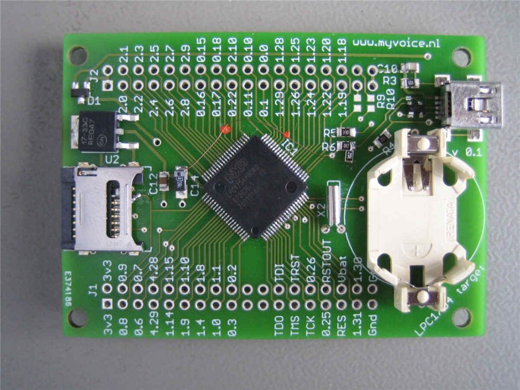
Programming
With the basic components in place it is time to do some real testing.
The Blinky example is compiled and downloaded using an LPC-Link module. This proves to be a bit of a problem ... There is no JTAG connector on the board so it is not that easy to connect the JTAG wires but in the end I manage. I can download and run the code.
Time to go ahead and write some real test software to check if all pins are soldered OK.
By now I discovered that not adding the JTAG header was a BIG mistake. Each and every time I need to connect a bunch of separate wires in order to connect the LPC-Link module. With a 10 pin header I could have used a standard JTAG cable - something to put on the new version of the board.
Together with two other things: I mis-interpreted the SD spec with respect to the micro-SD connections meaning that I swapped two pins and I forgot the pull up on the USB line.
Photos
 |
 |
 |
|